Complete CNC solution with Raspberry Pi
(this section is under construction...)
|
|
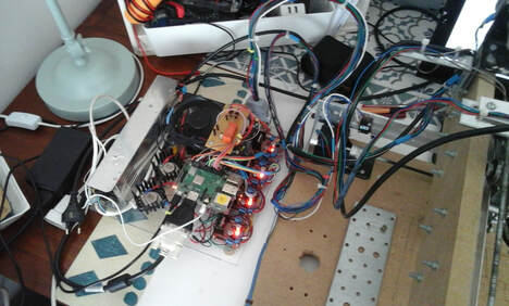
Except few components like stepper motors, H-Bridges,V-Groove bearings, switching power supply (12V-30Amp) and pullley all the other components are purchased from a local hardware store.
Raspberry Pi and GPIO connector

Raspberry Pi GPIO pin layout above will be used quite often further.
Introduction
The subject could be divided into 4 sections for a better explanation:
- 1. Producing and supplying the dxf format file
- 2. Main program written in Python (version 3.x preferred)
- 3. Electronic
- 4. Mechanic
1. Dxf formatted file
How to use a 2D or 3D software to make the drawing remains outside of our interest. But, the result must be a dxf formatted file :
AUTOCAD CAM METRIC
AUTOCAD CAM METRIC
The reason for that is easy to explain. The program will search keywords inside of a human readable text. Keywords are followed by some interesting parameters. These parameters are always located at specific distances versus keywords.
An example: The word CIRCLE is followed by Xc and Yc at offset 12 and 14. The Radius of the circle is located at offset 18. In terms of programming, offsets are "linefeeds".
Python program will skip the intermediate data (linefeeds) and extract what is useful for further calculus. In such situation, only the offset is taken into account. The program will not verify if the data at this location is meaningfull or not.
Be aware, there are different Autocad formats around. Algorithm of search may get lost because of offset variance between different versions of dxf format.
However, the program will display exactly the path to follow before starting to cut any garbage shape. The figure shown will be the exact mirror of X,Y steps for stepper motors.
Below is an example of dxf file contents where LINE, CIRCLE and POLYLINE may occur in any order. The offset for usefull data will always occur at same offset such as 12, 14 or 16 or 18,... depending on the shape (or figure).
LINE
Xs +12
Ys +14
Xe +18
Ye +20
CIRCLE
Xc +12
Yc +14
Radius +18
POLYLINE
VERTEX
X +14
Y +16
VERTEX
X +14
Y +16
...etc
SEQEND
....
another POLYLINE, CIRCLE or LINE may follow
LINE
Xs +12
Ys +14
Xe +18
Ye +20
CIRCLE
Xc +12
Yc +14
Radius +18
POLYLINE
VERTEX
X +14
Y +16
VERTEX
X +14
Y +16
...etc
SEQEND
....
another POLYLINE, CIRCLE or LINE may follow
2. Main program
The program "cnc-0.3-en.py", written in Python3, is about 2000 lines which is quite small compared to the job to accomplish. It is in beta version. When downloaded, the extension "python" must be replaced by "py". The object oriented programming style is not used.
The program itself is organized in several blocs each starting with something like:
# ----------------- IMPORT STARTS and ends with :
# ----------------- IMPORT ENDS
The major blocs are : IMPORT, GLOBAL VARIABLES, FUNCTIONS and MAIN (located toward the end)
The FUNCTIONS section contain all functions used in the program.
The role of def main(): (located around line 1900), consist to initialize the program and, in particular, the "Graphical User Interface" (GUI).
Because the environment choosen is event driven, there must be some connections between the main() and functions located above tthe main. These connections are declared by "bind" keyword inside main().
Which means "bind" one specific event, such as key hit or mouse clic, etc... to a particular function in order to trig a process (start a function...). An example would be something like:
wCan.bind('<Motion>', mouseMoves)
... where wCan is the identifier of the canvas (a blank area like a whiteboard on the screen...)
... the keyword "bind"
... Motion is the mouse movements
... mouseMoves (which could be any other word of your choice), is the name of the function where to jump when mouse moves. In other word, the mouse movements on the canvas can be followed (by X,Y coordinates).
Back to CNC. An important question is how to move the tool in X,Y surface and cut a clean shape. The answer need some clarification. First of all, dxf file will only deliver very basic, but crucial, information. An example is, LINE. This keyword is followed by the coordinates of starting point and ending point. So, what about intermediate points? Or, what to do and how to move the tool smoothly between these two end points.
The answer is, in one way or another, use an algorithm which must tell to stepper motors the best path to follow in order to join the starting point to the ending point.
Identifying or calculating the best suite (or series) of X,Y points between two edges is done by BRESENHAM algorithm which is exactly same algortihm for drawing a line to the screen. When the line is perfectly vertical or horizontal (or even 45°) there is no problem. But, if the line has a slope different than 0°-45°-90°, the suite of X,Y's must be aesthetically correct. This aesthetics is provided by BRESENHAM algorithm.
The path to follow for a CIRCLE is solved using basic trigonometric sin() and cos() functions (see processCircle() function).
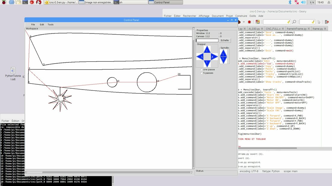
As an example, the picture below shows the image of some shapes to be cut. Red lines are 'tracks' to follow with tool in upper position (is away from material to be cut).
In this picture the canvas (white area) is larger then window itself. The vertical and horizontal scrollbars will give access to remainder of non visible figures.
Blue arrows in right panel are used to move the tool manually by few steps. The program being in development stage only basic functions are implemented.
The picture on the canvas is obtained from X,Y files for stepper motors. In other word, this image is the perfect copy of what the stepper motors will follow.
Below is an short extract of main flow of the program. It shows step after step what happens between user's clic on "Open" file and the image displayed to the canvas (screen's white area). A logical suite of functions will be activated between the two, i.e. a complex task is divided into several short functions.
In order to understand it might be useful to follow steps numbered from 1 to 7. The functions will call successively "one the next" :
User need to clic on Edit--> Show tracks to display the path between figures to be cut.
If everything seems to be OK, the last action could be Tools-->StartCNC to run the cnc.
In order to understand it might be useful to follow steps numbered from 1 to 7. The functions will call successively "one the next" :
- User clics from menu bar on "Open" file to choose a dxf file to be cut
- this action will automatically activate extractDXF() function ...
- ... which in turn will call buildPath() function which in turn call the next function ( pathOptim() )...
- ...pathOptim() will calculate the shortest paths to follow and call ( drawFormes() )...
- ...drawFormes() will display automatically figures to be cut etc...
User need to clic on Edit--> Show tracks to display the path between figures to be cut.
If everything seems to be OK, the last action could be Tools-->StartCNC to run the cnc.
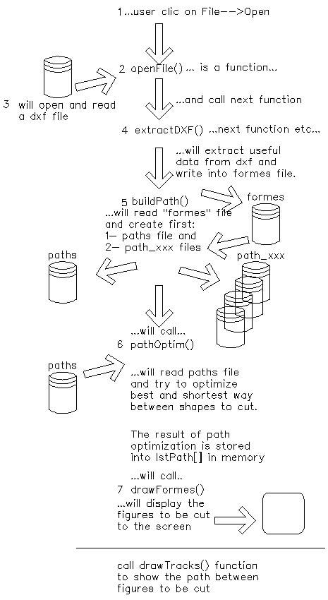
...after this last step the CNC is ready to run...
3. Electronic
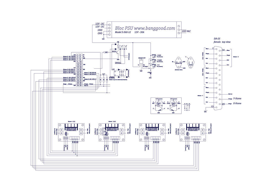
The schematics above show :
The Power Supply Unit (switching 12V - 30Amp) on top of the picture
Raspberry Pi GPIO at upper left
H-Bridges on bottom (2 of them are mounted in parallel to drive two stepper motos for X axis)
DB-25 type connector on the right (electronic could be physically separated from mechanics)
There are 3 X 2N3055 type power transistors mounted on heatsink to drop 12V to 5V
Right below the power supply there is a relay which supply 220V to the drill
Home switchs for X,Y and Z are returned to Raspberry Pi to signal that the tool is at Home position (0,0,0)
-------------------
Important as the electronic itself is the Power Unit, the fan (not shown) and the heatsink for 2N3055. Because the stepper motors require a lot of power which needs a good heat dissipation.
If you are interested in the software, please send an email to : [email protected]
You will receive the program
You will receive the program
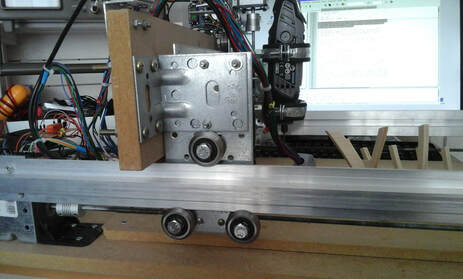
4. Mechanic
...coming soon...
